Bottesford Culvert Reline
June, 27, 2022
At a Glance
Location: Bottesford, Leicestershire
Clients: Dyer & Butler
Type of Project: Design of new masonry headwall, a new staircase, retaining wall and lining of a masonry culvert
Scope of Services: Civil Engineering
Project Summary
Design of new masonry headwall, a new staircase, retaining wall and lining of a masonry culvert. Bottesford Culvert is a masonry culvert which runs below two running lines. The proposal detailed in the original Form F001, was to reline the existing masonry culvert using segmented GRP sections. Due to deformations with the culvert, determined from a 3D ovalisation survey, VEDA proposed a CIPP liner as an alternative to GRP sections. On the downside of the structure, the culvert was to be extended to connect to a new headwall. Furthermore a set of access stairs to the track were to be installed.

VEDA were appointed by Dyer and Butler to design a new masonry headwall and extend the existing deformed culvert to the headwall using a CIPP liner. A new staircase was also to be constructed to provide access to the adjacent railway line.
A 3D laser survey of the structure was undertaken in order to determine the profile of the culvert. The survey indicated that the barrel was deformed approximately 2.5m from the downside headwall. Consequently, it restricted the outside diameter of the liner to 700mm. In accordance with Network Rail Standard Details, the liner proposed was to be 14mm thick and have a Modulus of Elasticity greater than 8500 Mpa. The annulus of the liner and any gaps were grouted.

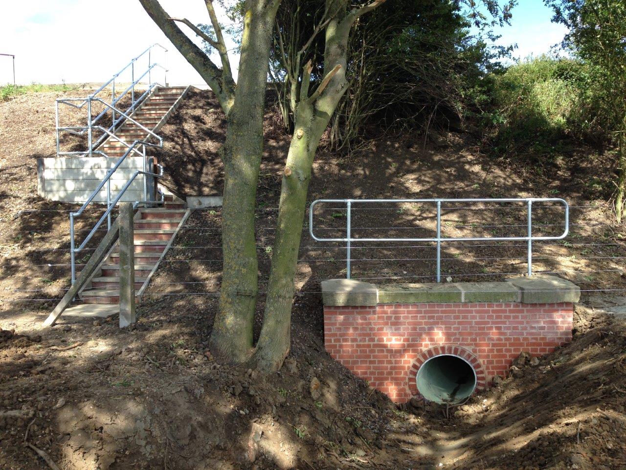
A new 1.71m high masonry headwall was designed and constructed 1.150m in front of the existing headwall, with a reinforced concrete base. The existing headwall was demolished to 300mm below proposed ground level and then buried.
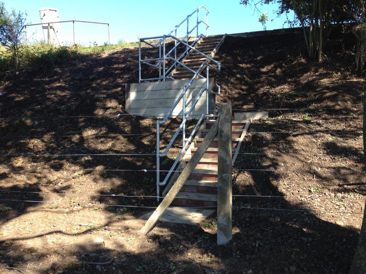
A set of access stairs was installed, starting adjacent to the downside headwall and finishing 2m from the nearest running rail, based on the maximum line speed. Due to the maximum incline allowed in the risers and goings, a dog leg at the intermediate landing was introduced with a requirement for soil to be retained. The soil retention design produced was a kingpost retaining wall around the intermediate landing and the steps which run parallel to the running line. The kingposts were 152x152x37UC sections, installed at a maximum of 2.3m centres and at a minimum embedment depth of 2.0m. Infill concrete panels were then horizontally stacked between the king posts and embedded a minimum 0.2m below ground level.
The works were installed as proposed.
